There's a red LED on Sonoff Basic
 Tomasz Torcz
Sonoff Basic is quite a nifty gadget. For less than $5 you get a WiFi-controlled mains switch, build around popular ESP8226 chip. That's right, an ESP, a relay, power supply, plastic shell and a green LED. Strangely enough, the LED has 3 connectors.
ITEAD, the manufacturer, was kind enough to provide electrical schematics for this gadget. Comparison with circuit board shows that the LED is infact a dual-color one. Red pin is used in 433MHz version of Sonoff (the RF). On the wifi module red pin is not connected to the chip, but quite accesible.
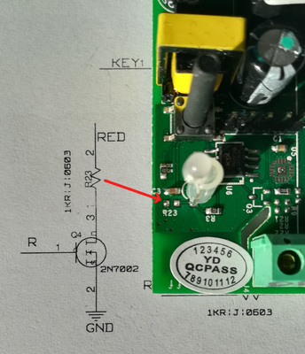
Notice how the traces go. On one side, the trace from LED goes to R3, and then to the place for Q3. The MOSFET is missing, but it's soldering pads are in place. Remember this location.
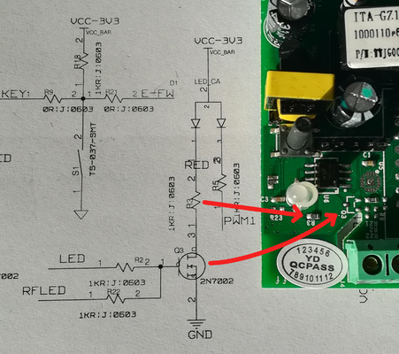
The trace for LED goes in another direction, too. First to R23 (missing on my board), then through a via to other side of board. Flip the board and the trace hits the place for Q4 MOSFET, also missing.
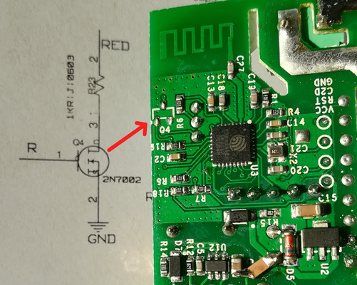
I suggest soldering a wire to Q3's contact. The resistor R3 is already in place, you need only a connection to GPIO. Either use exposed GPIO14 on 5-pin header, or – if you feel brave – you can solder the wire to GPIOs directly on ESP chip. You can see details on last 3 photos on Evert Dekker's site.
Now you can blink Sonoff's Basic LED in green and red.
Comments
Comments powered by Disqus